Monday, July 27, 2009

2W MiniBox Audio Amplifier

This circuit is simple and cheap, the components also easy to find. This amplifier can be feed by MP3 Player, MP4 Player, Walkman, Mini-Disc, iPod and CD players, computers and similar devices fitted with line or headphone output.
electronic circuit diagram

Component parts:
P1_____________10K   Log.Potentiometer

R1,R2__________33K
R3_____________33R
R4_____________15K
R5,R6___________1K
R7____________680R
R8____________120R
R9____________100R 1/2W Trimmer Cermet

C1,C2__________10µF 63V Electrolytic Capacitors
C3____________100µF 25V Electrolytic Capacitor
C4,C7_________470µF 25V Electrolytic Capacitors
C5_____________47pF 63V Ceramic Capacitor
C6____________220nF 63V Polyester Capacitor
C8___________1000µF 25V Electrolytic Capacitor

D1___________1N4148 75V 150mA Diode

Q1____________BC560C 45V 100mA PNP Low noise High gain Transistor
Q2____________BC337 45V 800mA NPN Transistor
Q3____________TIP31A 60V 4A NPN Transistor
Q4 ___________TIP32A 60V 4A PNP Transistor

SW1___________SPST switch
SPKR__________3-5 Watt Loudspeaker, 8, 4 or 2 Ohm impedance

Notes:
The amplifier(s) can be conveniently supplied by a 12V wall plug-in adapter.
Closing SW1 a bass-boost is provided but, at the same time, volume control must be increased to compensate for power loss at higher frequencies.
In use, R9 should be carefully adjusted to provide minimal audible signal cross-over distortion consistent with minimal measured quiescent current consumption; a good compromise is to set the quiescent current at about 10-15 mA.
To measure this current, wire a DC current meter temporarily in series with the collector of Q3.
Mini Audio Mixer circuit

This is simple mini audio mixer. This circuit consume low current due to the simple design. Also featuring three inputs with switchable high/low sensitivity and unusual level-control circuits, providing high overload margins and low-noise figures, proportional to gain-level settings.
Mini Audio Mixer circuit diagram


Component parts:
P1,P2,P3_________5K  Linear Potentiometers

R1,R11,R15_____180K
R2,R12,R16_______2M2
R3,R13,R17_____750R (See Notes)
R4,R14,R18_______1K
R5______________15K
R6_____________220R
R7_______________1K5
R8_____________820R
R9_____________150R
R10____________100K

C1,C6,C8_________1µF 63V Polyester or Electrolytic Capacitors
C2,C4,C7,C9____100µF 25V Electrolytic Capacitors
C3,C5__________220µF 25V Electrolytic Capacitors

Q1,Q4,Q5______BC550C 45V 100mA Low noise High gain NPN Transistors
Q2____________BC547 45V 100mA General purpose NPN Transistor
Q3____________BC557 45V 100mA General purpose PNP Transistor

J1,J2,J3________3mm or 6mm Mono Jack sockets
SW1,2,3,4______SPST Toggle or Slider Switches
B1_______________9V PP3 Battery
Clip for PP3 Battery

Notes:

  • When SW1, SW2 or SW3 are open the input sensitivity is suited to high-output devices like CD players, tuners, tape recorders, iPods, miniDisc players, computer audio outputs etc.
  • When SW1, SW2 or SW3 are closed the input sensitivity is suited to low-output, low-impedance moving coil or electret microphones.
  • Sometimes, the 750 Ohm value for R3, R13 and R17 resistors could be not easy to find. In this case, two 1K5 resistors wired in parallel can be used to replace each item.
  • To make a stereo mixer, all the parts must be doubled excepting R6, C3, C5, SW4 and B1.

Monday, July 20, 2009

Universal Pre-Amp circuit

This is the universal pre amplifier circuit diagram that can be used for common input such us microphone, cd player, tape recorder or other electronic circuit which require pre-amp.
Universal Pre-Amp circuit diagram


Download the schematic in PDF format

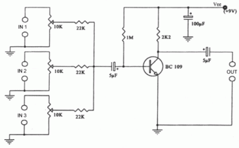
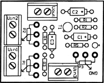
Simple Mixer circuit 3 Input

This is the very simple 3 input mixer for your audio system. You can add the number of input by adding some components for mixer input (P=10K R=22K). This circuit is only recommend for low and intermediate audio sound system. You need better mixer circuit for your high class audio system.

Here the Schematic diagram:
Simple Mixer circuit 3 Input  circuit diagram

This is component layout:
Simple Mixer circuit 3 Input  circuit diagram

And here the PCB layout:
Simple Mixer circuit 3 Input  circuit diagram

Thursday, July 16, 2009

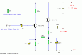
Condenser Mic preamplifier

Condenser Mic preamplifier circuit diagram

This is a very simple preamplifier circuit for condenser microphone. This mic preamplifier also can be used for dynamic microphone.

You can replace the BC549 with BC109C. For better audio result, use ultra low noise transistor BC650C.

Wednesday, July 15, 2009

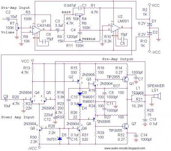
14Watt Audio Amplifier + pre-amp and tone control

This is the schematic diagram of 14 watt power audio amplifier included the pre-amp circuit and tone control circuit. I think this is complete audio system, just need an input and output (speaker)... :)
14Watt Audio Amplifier + pre-amp and tone control circuit diagram

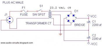
Use this power supply circuit:
14Watt Audio Amplifier + pre-amp and tone control circuit diagram

Sunday, July 12, 2009

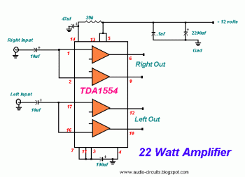
22W Audio Amplifier

This is simple and cheap 22W audio amplifier circuit for your car audio system or other audio appliances.
electronic circuit diagram

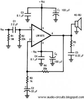
20W Audio Power Amplifier with LM1875

Here the 20W Audio Power Amplifier schematic diagram:
20W Audio Power Amplifier circuit diagram
This amplifier use LM1875 which offering very low distortion and high quality performance as the main component.

Feature:
• Up to 30 watts output power
• AVO typically 90 dB
• Low distortion: 0.015%, 1 kHz, 20 W
• Wide power bandwidth: 70 kHz
• Protection for AC and DC short circuits to ground
• Thermal protection with parole circuit
• High current capability: 4A
• Wide supply range 16V-60V
• Internal output protection diodes
• 94 dB ripple rejection
• Plastic power package TO-220

Saturday, July 11, 2009

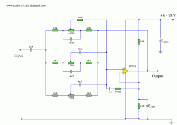
Equalizer 3 band

This is mono 3 band equalizer circuit. The circuit is simple, cheap and easy to built. You should make two circuits for your stereo audio system.
electronic circuit diagram


Supply voltage may be anything from 6 to 30 Volts. Maximum boost 20dB is only realized with maximum supply voltage.

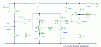
Tone Control circuit

Here the classic tone control circuit diagram.
Tone Control circuit diagram
This is mono tone control which contain 2 potensiometers to control the level of bass tone and treble tone. You could make the stereo tone control by duplicate this circuit, use stereo potensiometers and add mono potensiometer at input or output for balance adjustment.

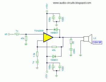
8 watt amplifier with TDA2030

This is cheap and easy audio amplifier circuit diagram.
8 watt amplifier with TDA2030 circuit diagram

Actually, the TDA2030 can give you 20watt output, but it was reduced to 8watt for greater output quality...