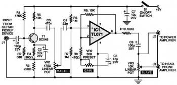
Right here is definitely the circuit of a electric guitar preamplifier circuit based TL071 that would accept any common guitar pickup. It's also versatile in that it has two signal outputs.
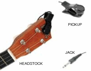
A common illustration of working with a pickup attached to a guitar headstock is shown in above image. The pickup unit contains a transducer on one end and also a jack on the other end. The jack can be plugged right into a guitar preamplifier circuit and then to a power amplifier system.
The pickup unit captures mechanical vibrations, generally from stringed instruments for example guitar or violin, and converts them into an electrical signal, which could then be amplified by an audio amplifier unit. It is most often mounted on the body of the music instrument, but may also be attached to the bridge, neck, pickguard or headstock.
The primary part of this preamplifier circuit shown in above circuit diagram is a single-transistor common-emitter amplifier with degenerative feedback in the emitter and a boot-strapped bias divider to safe optimum input impedance. Using the component values shown right here, the input impedance is higher than 50 kilo-ohms and the peak output voltage is about 2V RMS. Master-level-control potensiometer VR1 needs to be fine-tuned for minimal distortion.
The input from guitar pickup is fed to this preamplifier at J1 terminal. The signal is buffered and processed by the op-amp circuit wired close to IC TL071 (IC1). Set the gain utilizing preset VR2. The circuit has a master and a slave control. RCA socket J2 is the master signal output socket and socket J3 is the slave.
It really is considerably better to take the signal from J2 as the input to the audio power amplifier system or sound mixer. Output signals from J3 can be utilized to drive a regular headphone amplifier. Working with potensiometer VR3, set the slave output signal level at J3.
Assemble the circuit inside a metallic case. VR1 and VR3 ought to preferably be the types with metal enclosures. To avoid hum, ground the case and the enclosures. A well-regulated 9V DC power supply is important for this circuit. Even so, a standard 9V alkaline manganese battery may also be put into use to power the circuit. Switch S1 is a power-on/off switch.
Electric guitar preamplifier circuit based TL071, source: EFY Magz
About Audio Amplifier
An audio amplifier is an electronic amplifier that amplifies low-power audio signals (signals composed primarily of frequencies between 20 - 20 000 Hz, the human range of hearing) to a level suitable for driving loudspeakers and is the final stage in a typical audio playback chain.
The preceding stages in such a chain are low power audio amplifiers which perform tasks like pre-amplification, equalization, tone control, mixing/effects, or audio sources like record players, CD players, and cassette players. Most audio amplifiers require these low-level inputs to adhere to line levels.
While the input signal to an audio amplifier may measure only a few hundred microwatts, its output may be tens, hundreds, or thousands of watts. More explanation about power audio amplifier can be found at wikipedia.org
This is a video tutorial about how to a very simple audio amplifier based on the LM386 amplifier chip. It can be built for less than $20 (or might be less than $8 in some countries) and used to amplify any low level audio signal including a guitar, bass or mp3 player.
Watch the video:


No comments:
Post a Comment