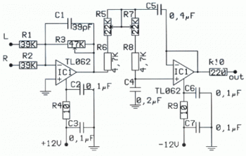
This is a Low band pass filter circuit especially designed for subwoofer loudspeaker. There are two input channels from stereo audio system, and the output was one output channel which connected to one subwoofer. Just like active speaker for computer.
Schematic Diagram:
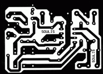
PCB Layout:
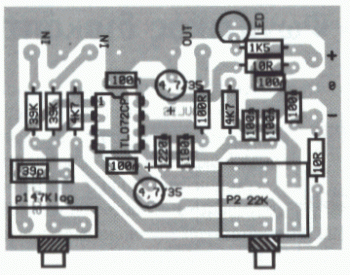
Component Placement:
Source:
http://www.high-voltage-lab.com/7/low-pass-filter-subwoofer
Visit the source page for detailed information about this low band pass circuit.


