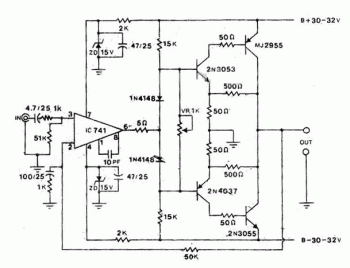
Here the Schematic diagram:
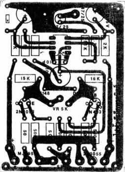
PCB layout:
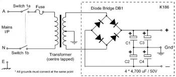
This amplifier require dual output power supply (+, ground and -). Use this power supply circuit:
For maximum performance, use 3-5 Ampere transformet with 24V secondary output.
You may use 5A Diode bridge or 4 pieces of single 5A diode.
About Audio Amplifier
An audio amplifier is an electronic amplifier that amplifies low-power audio signals (signals composed primarily of frequencies between 20 - 20 000 Hz, the human range of hearing) to a level suitable for driving loudspeakers and is the final stage in a typical audio playback chain.
The preceding stages in such a chain are low power audio amplifiers which perform tasks like pre-amplification, equalization, tone control, mixing/effects, or audio sources like record players, CD players, and cassette players. Most audio amplifiers require these low-level inputs to adhere to line levels.
While the input signal to an audio amplifier may measure only a few hundred microwatts, its output may be tens, hundreds, or thousands of watts. More explanation about power audio amplifier can be found at wikipedia.org
This is a video tutorial about how to a very simple audio amplifier based on the LM386 amplifier chip. It can be built for less than $20 (or might be less than $8 in some countries) and used to amplify any low level audio signal including a guitar, bass or mp3 player.
Watch the video:


No comments:
Post a Comment